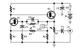
Parts List:
R1 = 5K6 - 1/4W
R2 = 1K8 - 1/4W
R3,R4 = 15K - 1/4W
R5 = 500R - 1/2W Trimmer Cermet
R6 = 330R - 1/4W
R7 = 470R - Linear Potentiometer
C1,C2 = 10nF
C3 = 100µF/25V
C4 = 470nF
Q1,Q2 = BC238
LP1 = 12V 40mA Filament Lamp Bulb (See Notes)
J1 = Phono chassis Socket
SW1 = SPST Slider Switch
B1 = 9V PP3
Circuit Notes:
- High gain transistors are preferred for better performance.
- The bulb must be a low current type (12V 40-50mA or 6V 50mA) in order to obtain excellent long term stability and low distortion.
- Using a bulb differing from specifications may require a change of R6 value to 220 or 150 Ohms to ensure proper circuit's oscillation.
- Distortion @ 1V RMS output is 0.15% using a 12V 40mA bulb, raising to 0.5% with a 12V 100mA one.
- Set R5 to read 1V RMS on an Audio Millivoltmeter connected to the output with R7 rotated fully clockwise, or to view a sinewave of 2.828V Peak-to-Peak amplitude on the oscilloscope.
- With C1, C2 = 100nF the frequency generated is 100Hz and with C1, C2 = 1nF frequency is 10KHz but R5 requires adjustment.
About Audio Amplifier
An audio amplifier is an electronic amplifier that amplifies low-power audio signals (signals composed primarily of frequencies between 20 - 20 000 Hz, the human range of hearing) to a level suitable for driving loudspeakers and is the final stage in a typical audio playback chain.
The preceding stages in such a chain are low power audio amplifiers which perform tasks like pre-amplification, equalization, tone control, mixing/effects, or audio sources like record players, CD players, and cassette players. Most audio amplifiers require these low-level inputs to adhere to line levels.
While the input signal to an audio amplifier may measure only a few hundred microwatts, its output may be tens, hundreds, or thousands of watts. More explanation about power audio amplifier can be found at wikipedia.org
This is a video tutorial about how to a very simple audio amplifier based on the LM386 amplifier chip. It can be built for less than $20 (or might be less than $8 in some countries) and used to amplify any low level audio signal including a guitar, bass or mp3 player.
Watch the video:

No comments:
Post a Comment